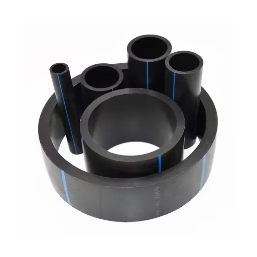

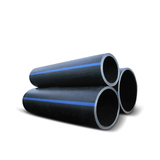
High-Density Polyethylene (HDPE) pipes have become an essential component in a wide variety of applications, ranging from water supply systems to industrial piping and beyond. Their unique combination of durability, flexibility, and resistance to corrosion makes them a preferred choice for engineers and contractors alike. However, with so many different sizes and diameters available, selecting the correct HDPE pipe for your specific needs can be a complex and daunting task. This article provides a comprehensive guide to understanding HDPE pipe sizes, ensuring you have the knowledge to make informed decisions. Whether you are working on a large-scale infrastructure project or a smaller installation, this guide will serve as a valuable resource to help you choose the right diameter for optimal performance and efficiency.
What Are the Standard HDPE Pipe Sizes?

What is the Nominal Pipe Size?
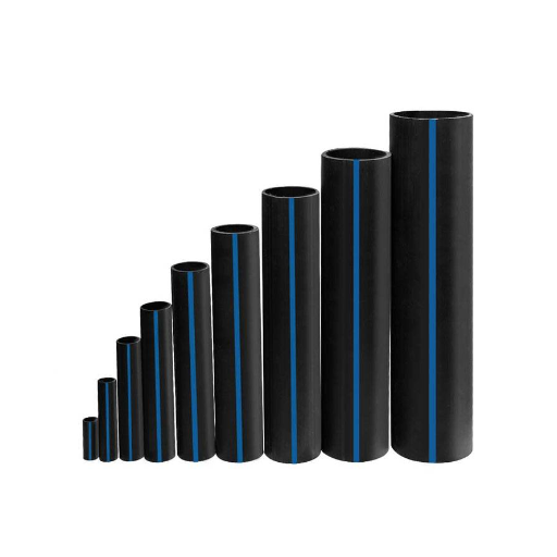
Nominal Pipe Size (NPS) is a standardized system used to specify the diameter of pipes, usually in inches, to promote uniformity within piping systems. It considers the outer diameter (OD), wall thickness, and inner diameter (ID) to determine the pipe’s capacity. Despite its name, NPS values do not always correspond exactly to actual measurements but rather function as a standard benchmark. Below is a table summarizing key Nominal HDPE Pipe Sizes:
|
Nominal Pipe Size (NPS) |
Outer Diameter (OD) |
Wall Thickness Range |
Pressure Rating |
|---|---|---|---|
|
1/2 inch |
0.84 inches |
0.06–0.12 inches |
Class PN6, PN10 |
|
1 inch |
1.32 inches |
0.08–0.16 inches |
Class PN6, PN16 |
|
2 inches |
2.38 inches |
0.09–0.19 inches |
Class PN6, PN20 |
|
4 inches |
4.50 inches |
0.18–0.37 inches |
Class PN10, PN25 |
|
6 inches |
6.63 inches |
0.22–0.55 inches |
Class PN10, PN25 |
|
8 inches |
8.63 inches |
0.25–0.72 inches |
Class PN16, PN20 |
|
10 inches |
10.75 inches |
0.30–1.00 inches |
Class PN16, PN25 |
|
12 inches |
12.75 inches |
0.37–1.18 inches |
Class PN10, PN25 |
|
16 inches |
16.00 inches |
0.44–1.50 inches |
Class PN6, PN16 |
|
20 inches |
20.00 inches |
0.55–1.87 inches |
Class PN6, PN16 |
This table outlines nominal HDPE pipe sizes for ease of selection at different project scopes. Refrain from using these pipes until you have confirmed local standards and operating conditions that might impact performance.
Exploring Metric and IPS Measurements
Differentiation by Metric and IPS (Internal Pipe Size) are two systems for defining and measuring the same pipes. A metric measurement is shaped upon a millimeter measuring system (mm) and is used dominantly in countries following the SI standards. These values often represent the outer diameter (OD) of the pipe, and are useful to accomplish more precision and standard compatibility across global suppliers.
In contrast to that, the IPS system is mostly used in North America, focusing on NPS units, which are pipes measured in inches. IPS sizes do not directly quote the OD but instead refer to a set of standard dimensions that includes a variety of wall thicknesses classified by schedules. This system is helpful for older infrastructure and these major industries that are used to the imperial unit system.
Choosing between metric and IPS, both having the usable standard but optimized for usability in different regions and applications geo-spatially, factors like regional practice, the design spec, and compatibility with pre-existing machines need to be considered. Understanding the unique attributes of both allows for the best optimization of the system for efficiency and longevity, ensuring high performance and durability. Always consider piping codes and engineering specifications in the decision-making process when making the final selection.
How Does Pipe Size Affect Water Flow Rate?
Calculating Flow Rate for Different Pipe Sizes
The water flow rate through a pipe is significantly determined by the diameter, length, material of the pipe, and even the pressure difference that drives the water flow. Taking an example of laminar flow, it is seen that the flow rate varies directly with the fourth power of the pipes internal radius. These observations suggest that even small changes in pipe diameter can result in marked increases in the flow rate, hence proper sizing is essential in applications which require specific delivery rates.
Another critical point for consideration is the water friction losses while moving through the pipe. The smaller the pipe diameter, the greater the resistance to fluid flow because of the increase in surface area contact relative to volume. This leads to a greater frictional pressure drop over the distance. In essence, this is captured using a friction factor, which, as cited, depends on the type of pipe material, the amount of roughness on the inside surface of the pipe, and the Reynolds number of the flowing fluid.
Now, specialized software with industry recognition in engineering design provide more precise flow simulation capabilities that estimate the flow in real-time, under different conditions and scenarios. The software can simulate the effects of bends, fittings, and even changes in diameter along a pipeline which the fundamental equations do not encapsulate because modern equations are highly complex.
Impact of Inside Diameter on Water Flow
A pipe’s internal diameter is directly related to how much water can flow through it and to its velocity. Fluid mechanics tells us that the area of a pipe, which is proportional to the inside diameter, directly affects the flow rate for a set amount of pressure. Water with greater flow rates and lower flow resistance requires less head loss, which is achieved with larger pipe diameters.
Cutting-edge computational fluid dynamics (CFD) software has enabled precise simulation with specific internal diameters and set flow pressures, which helps to visualize the impact on efficiency. For example, some flow rates are said to drop exponentially as the diameter increases. This poses a problem for systems that are designed to be energy efficient. Conversely, inefficient designs that increase costs from materials, coupled with expansions of unnecessary diameters, lead to greater inefficiencies.
Thanks to water management simulation tools, engineers can virtually model the flow of water through pipes of various shapes and sizes, even those that gradually narrow. These tools allow engineers to forecast and adjust maintenance, operations, and cost measures to performance benchmarks required for proper functioning. The empirical boundary conditions derived from actual research significantly improve the precision of hydraulic modeling when coupled with computational fluid dynamics.
What is the Role of Pressure Ratings in Pipe Selection?
Understanding Pressure Loss in HDPE Pipes
For the design of pipelines, the reduction of pressure for High-Density Polyethylene (HDPE) pipes is a primary concern, as it affects the efficiency and convenience of fluid transport systems. The most critical factors that affect pressure reduction are flow velocity, pipe diameter, internal surface roughness, and the viscosity and density of the fluid. In the case of any fluid, including HDPE, flowing through a pipe, work is spent in overcoming frictional forces between the fluid and the pipe wall. This energy is lost due to friction, and the pressure drop that results is referred to as the friction loss.
In the case of HDPE pipes, one of the most important pressure calculating formulas is the Darcy-Weisbach equation, which is also frequently used. This equation applies flow rate, pipe length, diameter, and friction factor, which depend on Reynolds number and pipe roughness. In addition to this, other fittings and valves also contribute to additional pressure loss that needs to be calculated in engineering design.
Contemporary computer applications alongside appropriate fluid dynamics software are capable of modeling pressure losses with great precision accuracy for HDPE systems, providing engineers with simulations and accurate data. These models often include empirical data, such as the Hazen-Williams coefficient for HDPE pipes that usually skirts between 150 and 160, showing that the internal surface is quite smooth and offers very little resistance.
Optimization of HDPE pipe networks can be achieved with minimal energy wastes and costs while still maintaining set standards of industrial performance through an understanding of sensor technology in conjunction with real-time monitoring systems. Achieving this balance promises lower operational costs while maintaining productivity standards in a wide variety of industrial and municipal applications.
How Pressure Requirements Influence Pipe Size
The pressure rating of a pipe — its Pressure Nominal (PN) value — relates to the thickness and diameter of the pipe walls. The transported substance’s medium force internally requires pipe walls thicker than the minimum being structurally sound and having longevity. For example, HDPE pipes rated at PN16 will have thicker walls than those rated at PN10 as both have the same outer diameter.
Moreover, other factors such as the pressure tolerance of various flows and the diameter of the pipe impact one another. Piping with larger diameters are associated with lowering pressure for long stretches as they enhance energy efficiency, whereas narrower piping is more useful when higher, more directed pressure is needed.
Bear in mind the necessity of pipes having safety margins and abiding standards like ISO 4427 or ASTM F714, along with the overlying calculations needed for optimization of pipe design. With the development of advanced modeling tools alongside computed simulations effectiveness in adapting precise pipe measurements with changing pressure becomes easier, and there can be a more balanced mixture of materials and cost-efficiency.
Choosing the Right Pressure Classes for Your Needs
It is important to gauge all relevant factors when choosing the pressure class of a piping system, including its safety and performance features. Operational pressures and temperature changes, along with the expected lifespan of the piping, need to be within the calculated maximum working pressure (MWP) limits. The piping class selection requires proper safety factors tailored to the specific requirements. Addressing the phenomena, including water hammer or surge events along with chemical processes, is equally important as they exert extreme forces on a given piping system.
Furthermore, a piping system needs to be selected using the right materials to determine the right pressure class. A case in point involves HDPE pipes, which are considered PN (Pressure Nominal) class pipes of grade PN6 to PN25 depending on their pressure-sustaining abilities. Compatibility with the fluid needs to be looked at as well, because chemical erosion or structural erosion would take place over time.
Improvements in analytical simulations as well as real-world testing procedures have enhanced the precision of pressure class selection. Incorporating these aspects improves operational effectiveness, while also minimizing maintenance expenses throughout the system’s life.
How to Determine the Appropriate Standard Dimension Ratio (SDR)?
What Does SDR Mean for HDPE Pipes?
The Standard Dimension Ratio (SDR) plays an important role as a criterion in the performance assessment of pipes made of High-Density Polyethylene (HDPE). It indicates the ratio between the outer diameter of the pipe and its wall thickness, serving as a comparative metric with other pipes in the same category about their structural and pressure-bearing abilities. For instance, an SDR 11 pipe has an outer diameter that is 11 times as thick as its wall. This helped designers and engineers balance the flexibility and strength of the pipes under different operational conditions.
Higher levels of SDR indicate lower pressure rating capabilities of the pipe. Pipes rated for high demanding uses such as water mains or industrial pipelines require thick walls which lower SDR values signify. On the other hand, drainage or sewer system pipes where cost savings become more useful, demand thinner walls and thus higher SDR values.
Contemporary data from simulations and field tests about SDR selection now integrates the more sophisticated components of chemical exposure duration, temperature variation, and internal pressure changes. This allows for optimization with regulatory criteria and enduring dependability in HDPE pipe installations, increasing overall project success.
Calculating SDR for Different Applications
|
Application |
Pipe Type |
Calculation Formula |
Key Point |
|---|---|---|---|
|
Water Distribution |
HDPE Pipe |
SDR = OD / Wall Thickness |
Ensures proper pressure resistance |
|
Sewer Systems |
PVC Pipe |
SDR = OD / Wall Thickness |
Minimizes risk of pipe deformation |
|
Irrigation Pipelines |
HDPE Pipe |
SDR = OD / Wall Thickness |
Optimized for low-pressure systems |
|
Gas Transmission |
PE Gas Pipe |
SDR = OD / Wall Thickness |
Maintains safety under high pressure |
|
Industrial Applications |
Reinforced HDPE Pipe |
SDR = OD / Wall Thickness |
Handles chemicals and temperature shifts |
|
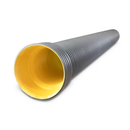
Stormwater Drainage |
Corrugated HDPE Pipe |
SDR = OD / Wall Thickness |
Designed for heavy flow conditions |
|
Mining and Slurry Pipelines |
HDPE Pipe |
SDR = OD / Wall Thickness |
Resists abrasion and slurry movement |
|
Pressure Sewer Systems |
PVC or HDPE Pipe |
SDR = OD / Wall Thickness |
Performance in pressurized waste systems |
This table serves as a credible aid for engineers and other professionals when choosing and computing the right SDR values for different uses to maintain and optimize system performance.
What Are the Industry Standards for HDPE Pipe Installation?

Steps for Proper Pipe Installation
- Site Prep: Start by performing a complete walkthrough of the site where the installation will be done to check the soil’s conditions, grading, and obstacles. Remove anything that may damage the pipe, like sharp debris, roots, and brittle objects. Check to make sure that the trench that is being dug is not too wide or deep and complies with ASTM D2321 or other industry standards. Trench bottoms should be level and free of pointed edges, which could put pressure directly onto the pipe.
- Handling and Storing Pipe: Pipes made of HDPE should be kept indoors or in a shaded area where the sun would not be able to directly hit them. The setting before the pipes are being installed should be in an area where the temperature remains at room level. Ensure that the pipes are put onto a stack that is flat and placed on stable ground where participants cannot walk on the bending edges. Do not pull the pipes along rough areas, which may damage the trim ends leading to the joint seal being damaged.
- Bedding Material Placement: Trench construction involves the installation of water pipes, and a particular requirement is granular sand or detached aggregates. Place a layer of approved bedding material, such as granular sand or crushed stone, at the bottom of the trench. The bedding layer must meet the prescribed thickness (usually not less than 4 to 6 inches in height). This helps with load distribution and minimizes the chance of localized pipe bending due to pressure. Consistent compaction of the bedding must be done to ensure that the pipe has an adequate permeable medium beneath it with even support.
- Pipe Joining: HDPE pipes are mechanucally connected in most cases through butt fusion, electrofusion, or using mechanical fittings. With butt fusion, confirm that pipe ends have proper alignment and that no dirt is present on the fused interfaces. Follow the guidelines set by the pipe or equipment manufacturer concerning the fusion method. This includes uniform heating of the pipe ends, applying appropriate pressure, and sufficient cooling duration to the joint for it to be leak-proof. Good alignment and cleaning the pipe surface are also very important for electrofusion.
- Pipe Placement in Trench: Carefully lower the assembled pipe into the trench utilizing safe lifting devices. Check that the pipe is laid properly on the formed bedding. Do not exceed the manufacturer’s minimum bending radius, as this will lead to undue stress on the pipe and may compromise its durability and functionality. It is equally important to check that the alignment does not exceed tolerance limits for optimal flow and system efficiency.
- Initial Backfilling: Intermediate backfill material, including sand or crushed stone, shall be placed on the pipe to a level of at least 12 inches above the crown of the pipe. Uniform compaction is to be applied to both sides of the pipe to eliminate all voids and provide lateral support to the pipe.
- Final Backfilling: Replace the trench with approved native soil or engineered fill, without large stones or debris, as this can cause localized pressure on the pipe. Expenditure of localized pressure is not allowed under firm surface settlement control. Verify that the final grade is within project specification tolerances. Compartmentalized final backfill is compacted in layers for optimal restoration of structural soil integrity.
- Inspection and Testing: Perform pressure and leak tests according to local codes or project requirements using hydrostatic or pneumatic testing methods. Verify all joints, connections, installations, as well as the entire system, within the system are functioning satisfactorily. Prepare compliance documentation regarding the tests done.
If these procedures, applicable standards, and manufacturer instructions are followed, the performance, durability, and lifespan of the HDPE pipe installations will be maximized.
Ensuring Compatibility with Existing Systems
Integrating an existing system with an HDPE pipe installation requires a complete evaluation of the infrastructure to check alignment and functionality. This checks the dimensions, pressure ratings, and materials of the existing system against the HDPE pipes. To prevent failure at the interfaces or inefficient operations, the compatibility review also needs to check the system functions, and failure modes of the system as well as the thermal expansion and chemical resistance properties of the material.
In terms of primary concern bounds maintenance free, long term reliability and seamless joints, transition fittings, flanges, or electrofusion couplings which were designed to connect HDPE to other materials must be utilized. The system’s operating parameters such as velocity, temperature and pressure need analysis to avoid over stressing the joints and other potential sources for material deformation.
Moreover, an evaluation regarding the control elements, such as valves and sensors, needs to be added to the review list, ensuring they adequately integrate and control the flow in the integrated system. Completeness in complying with relevant industry standards like ASTM or ISO helps effective interfacing of new and old components for robust, enduring features.
References
Frequently Asked Questions (FAQ)
Q: What are HDPE pipe dimensions, and why are they important?
A: HDPE pipe dimensions refer to the diameter and wall thickness of the pipes. Understanding these dimensions is crucial for ensuring optimal performance in various applications. The right HDPE pipe dimensions affect the flow capacity, pressure handling, and suitability for different industries.
Q: How do I choose the right HDPE pipe diameter for my project?
A: To choose the right HDPE pipe diameter, consider the flow capacity required for your application, the pipe’s pressure rating, and the specific requirements of the project. Consulting an HDPE pipe size chart can help in making an informed decision.
Q: What is the significance of the nominal size in HDPE pipes?
A: The nominal size of an HDPE pipe is a standardized dimension that helps in identifying the pipe’s outside diameter and wall thickness. It is crucial for ensuring compatibility with other pipes and fittings in a system.
Q: How does the pipe’s pressure rating affect its performance?
A: The pipe’s pressure rating indicates the maximum pressure the pipe can withstand. A higher pressure rating means the pipe can handle more stress and is suitable for applications requiring the pipe to withstand higher pressures.
Q: Why is corrosion resistance important for HDPE pipes?
A: Corrosion resistance is a key advantage of HDPE pipes, making them ideal for gas distribution and other applications where durability is essential. It ensures the longevity and reliability of the piping system.
Q: What is the role of the minimum wall in HDPE pipe specifications?
A: The minimum wall specification refers to the smallest allowable wall thickness of the pipe. It is crucial for maintaining the pipe’s strength and ensuring it can withstand the specified pressure and environmental conditions.
Q: How do HDPE pipes compare with other materials in terms of strength and suitability?
A: HDPE pipes are widely used due to their strength, flexibility, and corrosion resistance. They are suitable for a range of applications across various industries, offering advantages over materials like PVC in certain scenarios.
Q: What is PE4710, and how does it relate to HDPE pipe specifications?
A: PE4710 is a material designation for a specific type of HDPE resin known for its high strength and resistance to environmental stress cracking. It is often used in pipes that require a higher pressure rating and enhanced durability.
Q: How do different pressure ratings affect the use of HDPE pipes in various industries?
A: Different pressure ratings allow HDPE pipes to be used in a wide range of industries, from water supply to industrial applications. Selecting the appropriate pressure rating ensures that the pipe meets the specific demands of the application, ensuring safety and efficiency.